
Module 7 Homework Assignment
- Determine the transfer function of the phase-lead compensator that can be used with the follow open-loop transfer function in order to give a phase margin of 45°.
𝐺(𝑠)=5/ 𝑠(𝑠+1)
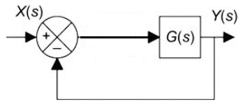
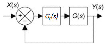
Include the Bode plots for the original system (𝐺(𝑠)) and the compensated system (𝐺𝑐(𝑠)𝐺(𝑠), where 𝐺𝑐(𝑠) is the transfer function of the phase-lead compensator). The Bode plots should show the phase margin (use the margin command or ltiview in MATLAB). Using a unit step input (𝑋(𝑠)=1𝑠), also plot the response to the closed-loop system with and without the phase-lead compensator (see figures below). Include both step responses on the same plot (use ltiview in MATLAB). How did changing the phase margin affect the step response? Include the MATLAB commands used.
2. Find the equation for the steady-state output (𝑦𝑠𝑠) for the following system with a step input (𝑋(𝑠)=1𝑠). Find the steady-state values when 𝐾𝑝=2 and 𝐾𝑝=48. Show that the steady-state values are correct by plotting the step response to the system when 𝐾𝑝=2 and 𝐾𝑝=48. Plot both systems on the same figure (use ltiview in MATLAB). Include the MATLAB commands used and a copy of the plot.
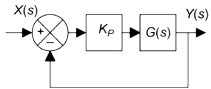
𝐺(𝑠)=1 / (𝑠2+2𝑠+2)
3. Simulate the 𝐾𝑝=48 system from question 2 in Simulink with a unit step input. Provide a picture of the Simulink model and the results from the Scope (make sure to scale the results of the Scope). Next add an integrator to the system so the controller has the form 𝐾𝑝(1+1𝑠) and use a unit step input. Provide a picture of the Simulink model and the results from the Scope. Finally add a derivative to your model so the controller has the form 𝐾𝑝(1+1𝑠+𝑠). Provide a picture of the Simulink model and the results from the Scope. How does the response of each system compare to each other qualitatively in terms of rise time, overshoot, damping, steady-state value, etc.?