Method of Submission: Electronic submission
Note: Submit through Assignment 2 submission box on StudyDesk. (Word or PDF formats are preferred. Neatly written and scanned reports will be also accepted). Attach your signed Assignment coversheet as submitted assignment without a coversheet will not be marked. The file name of the submitted assignment should be: CIV8803_SN_Assign2_###.doc or CIV8803_SN_Assign2_###.pdf, where SN corresponds to your serial number and ### corresponds to your Family name.
Students can get their serial number from USQ StudyDesk (see “Serial Number Sheet”).
You need to submit the assignment according to the following parameters correspond to your serial number (You will be penalised for using inappropriate parameters!).
A = Remainder (Serial number/2)
B = Remainder (Serial number/3)
C = Remainder (Serial number/4)
D = Remainder (Serial number/5)
Task 1 [40]
Determine the properties of the unidirectional glass fibre reinforced polymer composites given the following information in Table 1:
Table 1. Properties of glass fibres and polymer matrix for Task 1

Requirements:
1) Fibre fraction by weight. (5)
2) Glass thickness, resin thickness and total lamina thickness. (5)
3) Longitudinal and transverse moduli (E1 and E2), shear modulus (G12), major Poisson’s ratio (12), and tensile strength of the unidirectional (0o) glass fibre reinforced polymer composites. (20)
4) Transform E1, E2 and G12 to a global coordinate system with the axes oriented at 45° clockwise with respect to the corresponding glass fibre direction. (10)
Task 2 [60]
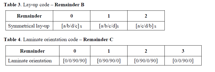
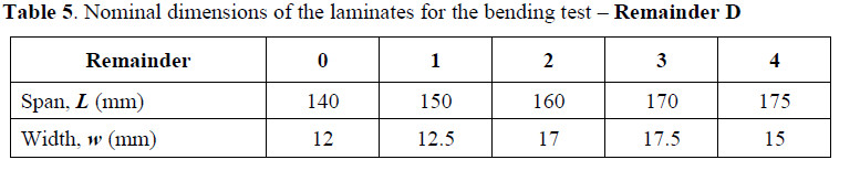
A hybrid composite laminate is made up of a combined glass and carbon fibres produced through the infusion process. Figure 1 shows an example of a hybrid lamina with orientation code [a/b/c/d] and the set-up for a 3-point static bending test. The mechanical properties and thickness of each lamina in the longitudinal direction is listed in Table 2. The stacking sequence is provided in Table 3 while the fibre orientation code for each case is provided in Table 4. The test span, L and width, w of the laminate is listed in Table 5

Using the classical laminated plate theory, determine the following:
1) Coefficients of the plate stiffness equations in the form of
[A] In-plane stiffness matrix
[B] Bending-extension coupling matrix
[D] Bending stiffness matrix (20)
2) The effective axial and flexural moduli of the symmetrical lay-up laminate. (10)
3) If the hybrid laminate with a symmetrical lay-up is tested in 3-point static bending with span L and width w (in Table 5), determine
Load at which the first layer failure occurs (10)
Maximum load P that the laminate could carry and the amount of midspan deflection. (20)
Task 3 [100]
The different fibre composite plies in Table 2 (in Task 2) are to be used in the design and manufacture of a composite bridge beam. The composite beam should be designed based on the performance requirements given in Table 6 to conform to the behaviour of existing timber bridge girders.
Beam property
Requirement
Tolerance
Maximum width 350 mm +0; -5 mm
Maximum depth 430 mm +0; – 5mm
Minimum moment at failure 650 kN-m -0
Shear capacity 340 kN -0
Flexural stiffness, EI 30 x 1012 N-mm2 +/- 10%
If the beam will be simply supported and designed to carry a uniformly distributed load, W shown in Figure 2, determine the following:
1) The design modulus and strength of the fibre composites laminate in Table 2 if they are produced in fully automated and fully-controlled temperature and humidity factory and post-cured in accordance with the manufacturer’s specification. The composite beam is to be used permanently in near-coastal area with a service temperature of up to 45oC. Assume the HDT of composites is 100oC. (20)
2) Details of the cross-section including information on the number and orientation of the plies, flexural stiffness, maximum moment and shear capacities of the beam. (30)
3) If the bridge beam has a span, L of 12 m, determine the maximum uniformly distributed load, W and the amount of midspan deflection of the beam. (20)
4) If the deflection is limited to “span/360 (mm)”, determine and provide comments on the following:
a. Uniformly distributed load, W the bridge beam carries. (15)
b. Strength factor. (5)
c. Deformability factor. (5)
d. Robustness factor. (5)

Task 4 [50]
A bi-axial glass fibre laminate is tested in the longitudinal direction in tension and compression. The average dimensions of the laminates and the load and strain readings for each test were measured and recorded. The results of the test are provided in the folder Assignment 2 Task 4 – Laminate test results. Tables 7 and 8 show the parameters used to determine the following properties of the laminates:
1) Draw the stress-strain curve of the glass fibre laminates in tension and compression. (10)
2) The tensile and compressive moduli of the laminates. (10)
Note: Determine the elastic modulus from the linear portion of the stress-strain curve between 1000 and 3000 microstrains.
3) The maximum tensile and compressive strength. (10)

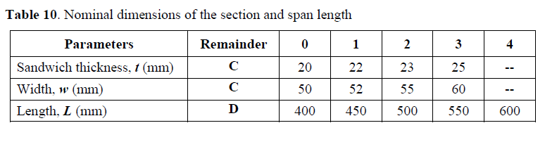
The tested glass fibre laminates are used as top and bottom skins of a sandwich structure with a high strength core material. The mechanical properties of the core material are given in Table 9 while the nominal dimensions of the sandwich beam (thickness, t and width, w) and span, L are to be selected in Table 10 for your particular case. If the simply supported fibre composite sandwich beam is designed to carry a uniformly distributed load, W shown in Figure 3, determine the maximum uniformly distributed load, W and the amount of midspan deflection of the sandwich beam when the first failure of the skin (either the top or bottom skin) or core occurs. (20)