
sample answer:
https://docs.google.com/document/d/1JFnB6TXbRSFyvi5oclkgONoY735bBHoA/edit?usp=sharing&ouid=102635727904023935419&rtpof=true&sd=true
Whatsapp – +91-9976287245
In this assignment, you need to demonstrate your understanding of concepts of load path and load estimation, analysis and design of a steel structure, i.e. a portal frame, primarily, modules 2, 7-9 and 11.
Project Brief
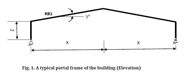
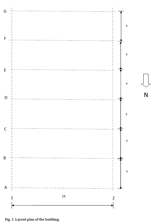
A new industrial building is to be constructed at 192 Bowhill Road, Willawong, Brisbane, Queensland (please use Google map as reference), as shown in the attached drawings, Figures 1 and 2. Refer to the north direction in Fig. 2 that shows the orientation of the building. The building will be made of structural steel pitched (pitch 5o) portal frames. All the joints of the portal frame are rigid connections. The connections between the columns and the footings are pinned (bolted).
The sidewalls and the roofs of the building will be covered with metal sheeting. The metal sheeting sits on purlins on roof and sits on girts on side walls. The roof sheeting will be fixed to steel purlins running along the length of the building (north-south). Purlins will be attached to the top flange of the roof beams and hence, would provide lateral restraint to the top flange of these beams. Similarly, girts attached to the outer flange of columns would provide lateral restraint to columns.
There are typical glazed windows (L = 2500 mm, H = 1000 mm, 20 mm thick) between A-B, C-D and E-F grids along grid 1 and on alternate bays (B-C, D-E and F-G) along grid 2, at an elevation of 1500 mm above the floor. Assume that the windows will be centrally placed between 2 grid lines. There is a rolling shutter of 1220 mm wide and 2200 mm high along grid A only. The floor is made of reinforced concrete. Assume that lateral bracing systems along grids 1 and 2 that would carry the wind loading in the longitudinal direction. You do not need to design the bracing system. Because of the bracing system in place, the columns have pinned connections at the top in the longitudinal direction. On the other hand, the portal frames will carry the wind loading in the transverse direction. Assume that the building is enclosed for wind load calculations.
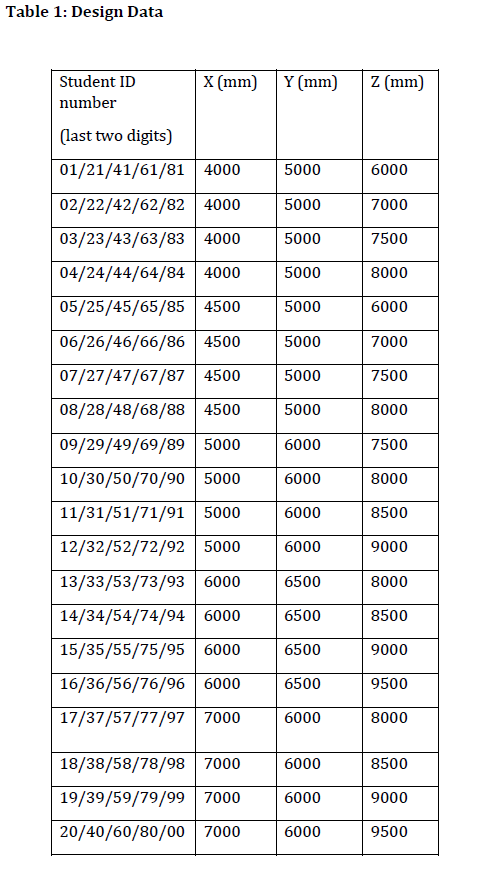
Take appropriate values of X, Y and Z as appropriate from Table 1 depending on the last two digits of your Student ID number. Assume appropriate realistic values for other design data that are not provided.
Use appropriate standards (AS1170.0 2002, 1170.1 2002 and 1170.2 2011 R2016) for the estimation of loads and AS4100 1998 using One Steel of Grade 300 for steel design.
Use linear elastic analysis and limit state design
Ignore secondary effects.
- Problem statement
Q1. Load estimation (80 marks)
a) Calculate the wind loads acting on the typical portal frame shown in Fig. 1 (60 marks)
Assume no shielding, Ms =1.0. Only consider the easterly and northerly wind directions. Determine the followings:
Design wind speed and pressure
Design pressures and Cfig for external surfaces: windward, leeward, sidewalls and roof, assuming Ka = 1, α = 5o
Design pressures and Cfig for internal surfaces which may give the worst uplifted case for the roof
Determine the worst uplifted case for the roof and worst case for the columns.
b) Calculate the loads (DL +LL) acting on the typical portal frame. (20 marks)
Q2. Purlin Design (20 marks)
a) Select purlin spacing to suit sheeting and geometry
b) Determine design loads and select purlin from tables
Use the same purlin section for girts, no separate design is required.
Q3. Analyse the portal frame using Strand7 (50 marks)
Analyse the portal frame on Grid B using appropriate loading combinations for strength and serviceability considerations using Strand7. Display the bending moment, shear force and axial force diagrams and deflected shapes of the frame.
Q4. Roof Beam design (50 Marks)
Design a typical roof beam (RB1) on Grid B for strength and serviceability requirements. Use One Steel 300 grade Universal Beam sections.
Q5. Column design (50 Marks)
Design a typical column B1 for strength and serviceability requirements. Use One Steel 300 grade Universal Beam sections.
Note the following:
The assignment would contain one set of safe design for all structural elements showing all the necessary steps and all your trial designs should go in the Appendix in proper sequence. Marks will be given for systematic design with comments.
If you are using worksheet (Excel type) for iterative design calculations, once your design is finalised, you need to show that set of safe design calculations clearly. Work sheets will not be marked.
Mention all the relevant clauses of the code at the left/right margin throughout the design so that they can be checked.
If you use incorrect parameters, you can lose up to 20% of the total marks of the assignment.