
Contact: +91-9976287245 (Whatsapp)

In this assignment, you need to demonstrate your understanding of concepts of load path and load estimation, analysis and design of footings and retaining wall, so primarily, modules 1-5.
DESIGN BRIEF
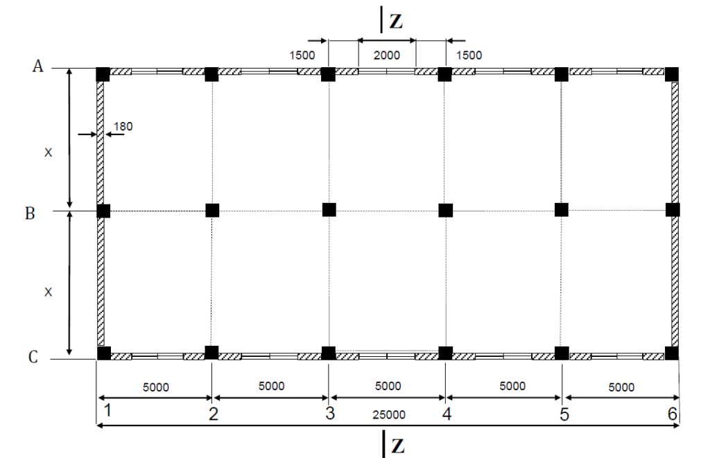
The figures above show a typical floor plan and section elevation of a three-storied reinforced concrete office building to be constructed at Townsville. Drawing is not to scale. All units are in mm. This is a framed reinforced concrete building monolithically cast with the beams along grids A, B and C supporting the RC floor. The beams transfer the load to the columns rigidly connected to them at their supports. Assume that the thickness of the floor slabs and the roof slab are 200 mm and they all have the same beam layout. Slope of the inaccessible roof (except for maintenance) can be ignored and can be considered as flat. The roof has an overhang of 300 mm all around the building as shown in the fig. above. The ground floor slab is slab-on-ground so the load will be transferred directly to the soil below. Beams along grids 1 and 6 are of 300 mm width x 600 mm deep and support the brick walls completely and the slab as well.
Because of the space issues and to eliminate the differential settlement, combined footings are to be designed. In reality, all the columns of B row, B1 to B6 will be combined to a single footing or A1, B1 and C1 etc. can be combined to a single footing, all the columns of the building will be connected a single raft footing. For the assignment purpose, the design is simplified, so combined footings are to be designed for columns B1 and C1, B2 and C2 etc. All the columns are rigidly connected to footings. All the glass windows are 2000 mm x 1800 mm x 20 mm. The brick masonry wall is 180 mm thick.
Because of the difference in elevation between the ground level where the building will be constructed and the adjacent area, a suitable retaining wall is to be designed to accommodate the step change. The retaining wall is parallel to grid 1 and is only on the left side of the building (not shown in fig.). The wall will retain soil only on one side, i.e. on the side of the building. Because the wall is close to the building, assume that a part of the building load is to be carried by the retaining wall. In the absence of exact calculations, assume that the building loads up to Grid 3 will be carried by the retaining wall and this load can be considered as a surcharge load acting on the retaining wall. The height of the wall is the difference between the GL of the building and the GL of the bottom level of the wall, which is provided in Table 1 below. In reality, the calculation is more complicated, things have been simplified for the assignment purpose. If you want to do precise calculation, proceed without any problem. Assume data not supplied, however, explain the reasons of the assumed values.
DESIGN DATA
Concrete characteristic strength, f’c = Y MPa
Yield strength of reinforcing steel, fy = 500 MPa.
Density of RCC, = 2500 kg/m3.
Glass windows are of unit weight, = 2600 kg/m3.
Exposure classification: A2.
Take appropriate values of X and Y and other values as appropriate from Table 1 depending on the last two digits of your Student ID number. Assume appropriate realistic values for other design data that are not provided.
Assume that a shear wall (not shown in fig.) would carry the lateral wind loading. Ignore this for preliminary design.
All design and detailing should be in accordance with AS 3600 2009 and loading should be in accordance with AS 1170.0, AS1170.1.
Ignore secondary effects.

PROBLEM STATEMENT
Q1. Load estimation (50 marks)
a) Calculate the loadings acting on the columns i) B1 and ii) C1 at the footing level. Use
approximate methods (based on codes) for appropriate load combinations OR do a
frame analysis using Strand7 as per cl 6.9.3 AS3600 2009. (25+25 marks)
Q2. Footing design and detailing (90 marks)
a) Design a combined footing (dimensions L, W and D) for columns B1 and C1 ONLY for
strength and serviceability requirements. Ensure that the soil pressure distribution
below the footing is uniform. Assume that clear cover at the bottom is 75 mm and cover
all around is 50 mm. (45 marks)
b) Design the reinforcement required and draw the reinforcement detailing clearly
showing at least 2 views. (45 marks)
Q3. Retaining wall design (110 marks)
a) Calculate all the loads acting on the RC cantilever retaining wall for the height given in
Table 1. The backfilled soil is crushed gravel deposit with the properties: c=0 kPa,
30 , 19 o kN/m3. The subsoil below the base is clay with c=6 kPa, 30 , 19 o
kN/m3 with an allowable bearing capacity qa = 250 kPa. Neglect the effect of wind and
seismic load (if any). Assume clear cover at the bottom of the base is 75 mm and cover
all around is 50 mm. Draw a sketch of the wall showing the forces acting on it.
b) Design the retaining wall for stability and serviceability requirements.
(35 marks)
c) Design the reinforcement required. Drawing showing reinforcement detailing not required.
Note the following:
The assignment would contain one set of safe design for all structural elements showing all the necessary steps and all your trial designs should go in the Appendix in proper sequence. Marks will be given for systematic design with comments.
If you are using worksheet (Excel type) for iterative design calculations, once your design is finalised, you need to show that set of safe design calculations clearly. Work sheets will not be marked.
Mention all the relevant clauses of the code at the left/right margin throughout the design so that they can be checked.
If you use incorrect parameters, you can lose up to 20% of the total marks of the assignment.